Products
Contact Us
Tel: +86-577-86866707
Fax: +86-577-86866707
Mob: +86-15906484621
E-mail: kaysenflange@hotmail.com
ASME B16.48 Spectacle Blind Flange Spade, Ring Spacer
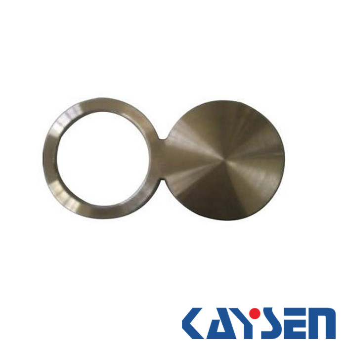
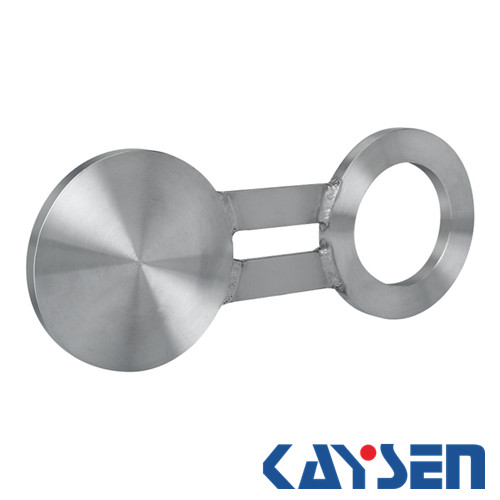
ANSI B16.48 forged spectacle blind flange class 300
Standard: ANSI B16.48
Flange type: spectacle blind Flange Raised Face
Size range: 1/2''-24''
Pressure: Class 300
Material: Stainless steel , Alloy Steel , Carbon Steel
Standard: ANSI B16.48
Flange type: Spectacle Blind Flange Raised Face type 4
Size range: 1/2"-24"
Pressure class: Class 300
Surface treatment:Anti-rust oil,transparent/yellow/black,Anti-rust paint,Zinc,Hot dipped
galvanized
Specialize:As per drawing
Material of Spectacle Blind Flange Raised Face:
Stainless Steel Material of Spectacle Blind Flange Raised Face:
ASTM A182F304,304L,304H,316,316L,316Ti,310,310S,321,321H,317,347,347H,904L
Duplex stainless steel UNS S32304,S31803,S32205.
Super Duplex stainless steel UNS S32750/S32760/S31260/S32550/S32707
Carbon Steel Material of Spectacle Blind Flange Raised Face:
ASTM A105, Q235, A350 LF2,ASTM A694 F42/F46/F52/F60/F65/F70/F80
Alloy Steel Material of Spectacle Blind Flange Raised Face:
ASTM A 182, GR F1,F5, F9, F11, F22, F91
Copper&Nickel Alloy Material of Spectacle Blind Flange Raised Face:
CU/NI 90/10, CU/NI 70/30
Nickel Alloy Material of Spectacle Blind Flange Raised Face:
Monel 400 & 500, Inconel 600 & 625, Incolloy 800, 825, Hastelloy C22,C276
Surface treatment:Anti-rust oil,transparent/yellow/black,Anti-rust paint,Zinc,Hot dipped
galvanized
Usage:Oil field, Offshore,Water system,Shipbuilding,Natural gas,Electric power, Pipe
projects,etc.
Standard: ANSI B16.48
Flange type: spectacle blind flange Raised Face
Size range: 1/2''-24''
Pressure class:Class 300
Material : Stainless steel , Alloy Steel , Carbon Steel

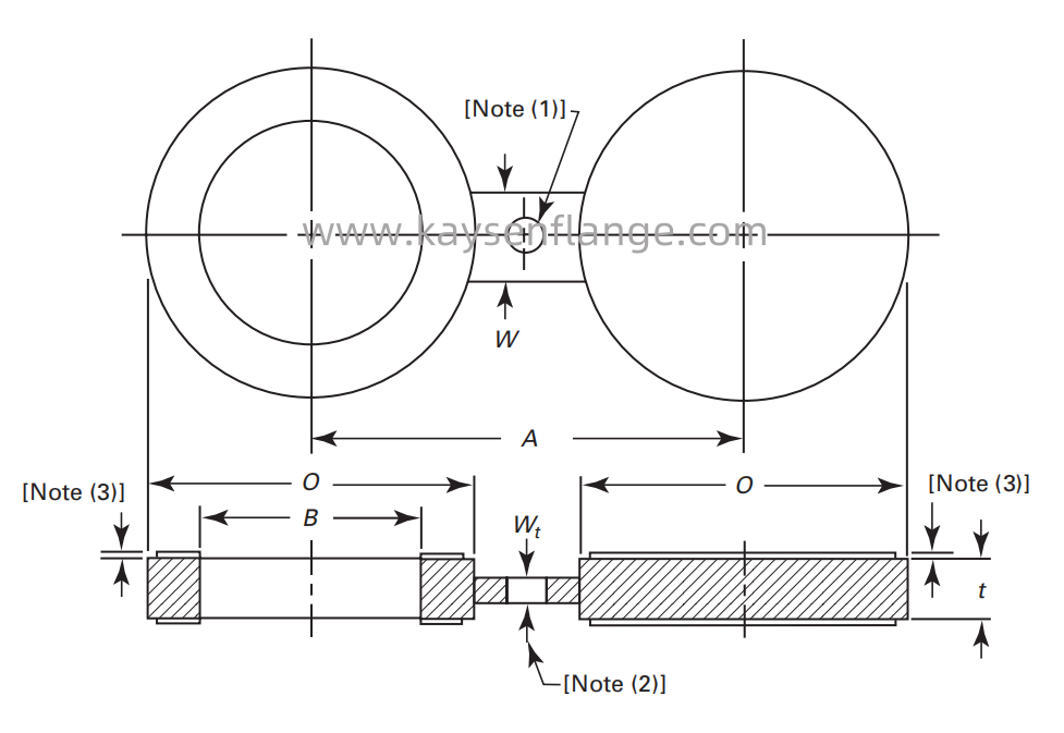
| Dimensions of Class 300 Raised Face Figure-8 Blanks | |||||
| NPS | Inside Diameter,B, mm |
Outside Diameter, O, mm |
Centerline Dimension,A, mm |
Thickness,t, mm |
Web Width,W,mm |
| 1/2 | 16 | 51 | 65 | 6.4 | 38 |
| 3/4 | 21 | 64 | 80 | 6.4 | 38 |
| 1 | 27 | 70 | 90 | 6.4 | 38 |
| 1 1/4 | 42 | 79 | 100 | 6.4 | 38 |
| 1 1/2 | 48 | 92 | 115 | 6.4 | 38 |
| 2 | 61 | 108 | 125 | 9.7 | 51 |
| 2 1/2 | 73 | 127 | 150 | 9.7 | 51 |
| 3 | 89 | 146 | 170 | 9.7 | 64 |
| 3 1/2 | 102 | 162 | 185 | 12.7 | 64 |
| 4 | 114 | 178 | 200 | 12.7 | 64 |
| 5 | 141 | 213 | 235 | 15.7 | 76 |
| 6 | 168 | 248 | 270 | 15.7 | 76 |
| 8 | 219 | 305 | 330 | 22.4 | 76 |
| 10 | 273 | 359 | 385 | 25.4 | 102 |
| 12 | 324 | 419 | 450 | 28.4 | 102 |
| 14 | 356 | 483 | 515 | 31.8 | 108 |
| 16 | 406 | 536 | 570 | 38.1 | 108 |
| 18 | 457 | 594 | 630 | 41.1 | 114 |
| 20 | 508 | 651 | 685 | 44.5 | 121 |
| 24 | 610 | 772 | 810 | 50.8 | 140 |
GENERAL NOTE:
1.Dimensions are in millimeters
2.Hole size (where required due to bolt spacing) shall be the same as the flange bolt hole and located such that it will not interfere with bolting between two flanges.


